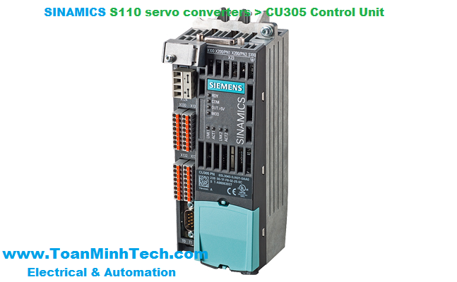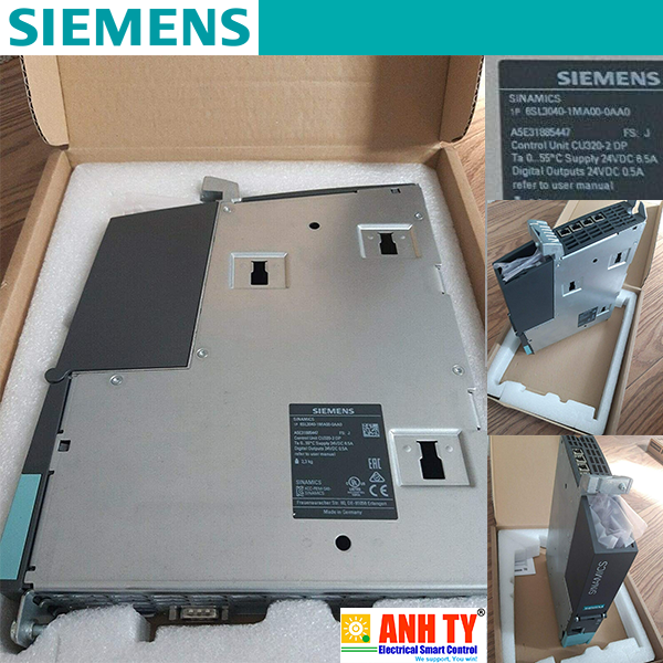


CU305 PN Control Unit
The CU305 Control Unit for the communication and open-loop/closed-loop control functions of a SINAMICS S110 is combined with the PM340 Power Module to create a powerful single drive.
The CU305 Control Unit features the following connections and interfaces as standard:
- Fieldbus interface + CU305 PN: 1 PROFINET interface with 2 ports (RJ45 sockets) with PROFIdrive V4 profileThe CU305 Control Unit controls the PM340 Power Module via the PM-IF interface.
A BOP20 Basic Operator Panel can also be snapped directly onto the CU305 for diagnostic purposes. For comprehensive diagnostics and commissioning functions, an Intelligent Operator Panel (IOP) can be connected to the RS232 interface.
DRIVE-CLiQ motors can be connected to the integrated DRIVE-CLiQ socket as well as Sensor Modules (SMC) to permit the operation of motors without a DRIVE-CLiQ interface.
The status of the CU305 is indicated via multi-color LEDs.
The CU305 can be operated optionally with a memory card. The firmware and project data are stored on the plug-in card underneath, so that the CU305 can be replaced without the support of software tools. This memory card can also be used to perform standard commissioning on multiple drives of identical type. The card is available as an empty memory card or containing the latest drive firmware version. The card also contains the safety license for the Extended Safety Functions. To use these Extended Safety Functions, a memory card containing the safety license must be permanently inserted.
The CU305 and other connected components are commissioned and diagnosed with the STARTER commissioning tool.
Connection example of CU305 Control Unit
|
|
CU305 PN / CU305 DP Control Units PROFINET: 6SL3040-0JA01-0AA0 PROFIBUS: 6SL3040-0JA00-0AA0 |
|---|---|
|
Power requirement At 24 V DC, max. |
0.8 A for CU305 incl. 350 mA for HTL encoder + 0.5 A for PM340 Power Module |
|
Conductor cross-section, max. |
2.5 mm2 |
|
Fuse protection, max. |
20 A |
|
Digital inputs |
In accordance with IEC 61131‑2 Type 1 3 floating fail-safe inputs 5 floating digital inputs |
|
-3 ... +30 V |
|
-3 ... +5 V |
|
15 ... 30 V |
|
6 mA |
|
|
|
15 μs |
|
55 μs |
|
|
|
5 μs |
|
5 μs |
|
1.5 mm2 |
|
Digital outputs (continuously short-circuit-proof) |
1 fail-safe digital output 4 bidirectional non-floating digital inputs/digital outputs |
|
24 V DC |
|
100 mA |
|
150 μs |
|
1.5 mm2 |
|
Analog input |
-10 ... +10 V |
|
15 kΩ |
|
Encoder evaluation |
|
|
24 V DC/0.35 A or 5 V DC/0.35 A |
|
500 kHz |
|
100 ... 250 kBaud |
|
30 bit |
|
|
|
100 m (328 ft) (only bipolar signals permitted) 3) |
|
100 m (328 ft) for unipolar signals 300 m (984 ft) for bipolar signals 3) |
|
100 m (328 ft) |
|
Power loss |
<20 W |
|
PE connection |
M5 screw |
|
Dimensions |
|
|
73 mm (2.87 in) |
|
|
|
|
|
Weight, approx. |
0.95 kg (2.09 lb) |
|
Approvals |
cULus |
1)The specified delay times refer to the hardware. The actual reaction time depends on the time slice in which the digital input or output is processed.
2) In order to use the digital outputs, an external 24 V power supply must be connected to terminal X124.
3) Signal cables twisted in pairs and shielded.
